A pulse-jet dust collector earns its keep when your process is producing dust continuously and you cannot afford to shut down filtration just to clean the bags. If you run a grinding line, a casting finishing cell, a bulk bag unloading station, or a feed ingredient transfer system, you already know the real problem is not “capturing dust once” – it is keeping stable suction and consistent emissions performance hour after hour, shift after shift.
Below is a practical engineering explanation of how does a pulse jet dust collector work, with the operational details that matter for plant uptime, worker exposure control, and defensible compliance documentation.
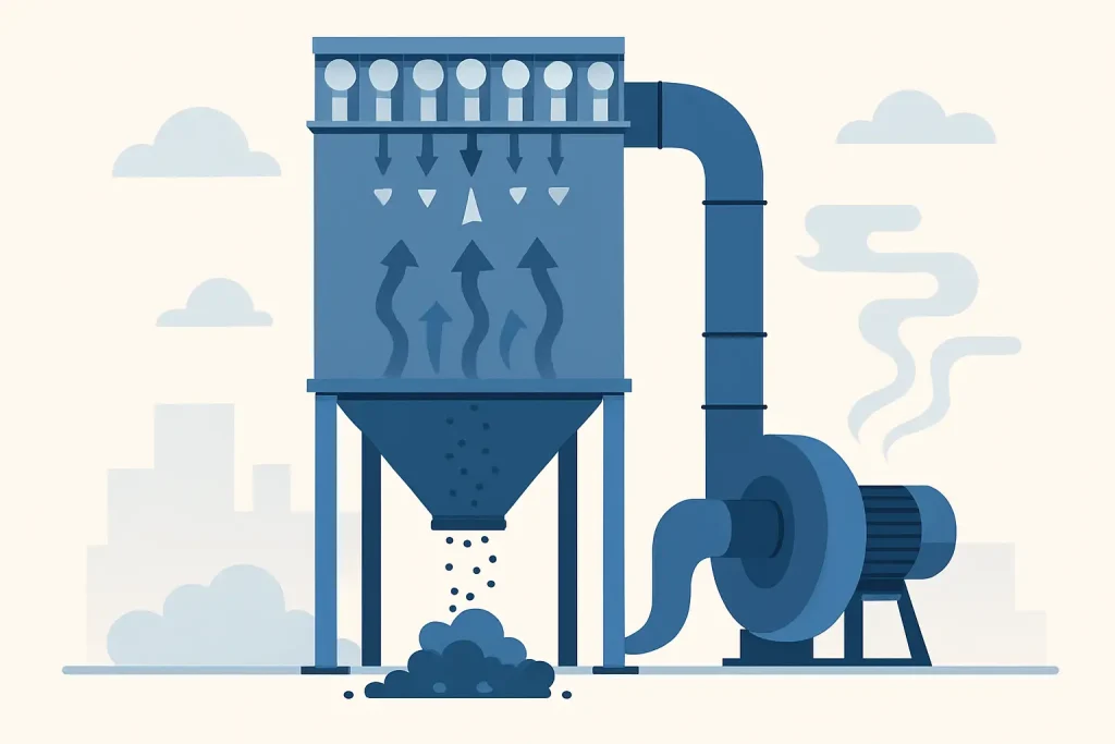
How does a pulse jet dust collector work?
At a high level, a pulse-jet dust collector pulls dust-laden air from your pickup points (hoods, enclosures, duct branches) into a collector housing where filter bags or cartridges capture particulate. Clean air passes through the filter media and exits to the fan stack or to a return-air plenum (only if your risk assessment and local requirements allow).
What makes it “pulse-jet” is the cleaning method. Instead of taking sections offline for shaking or reverse-air cleaning, the collector uses short bursts of compressed air to dislodge accumulated dust from the filters while airflow continues. That “online cleaning” is why pulse-jet units are commonly selected for higher dust loadings, continuous duty, and applications where stable draft is critical.
From an engineering standpoint, the system is best understood as four interacting loops: airflow generation, filtration (dust cake formation), pulse cleaning, and dust discharge.
Step 1: Airflow and capture – the part that determines whether you meet LEV intent
Everything starts at the hood or pickup point. Your fan creates negative pressure in the ducting network, producing capture velocity at the source. If capture velocity drops, dust escapes into the work area, and your LEV performance becomes questionable.
The dust collector is not just a “box with bags.” It is a pressure-loss component in a full ventilation system. As filters load with dust, resistance rises. If the fan is not sized correctly or control logic is poor, the system drifts – suction decreases at the farthest pickup points first, then the rest follow.
This is why duct design, balancing, and commissioning are inseparable from the collector selection. Even a well-built collector cannot compensate for undersized duct branches, poor hood geometry, or excessive bends that add static pressure and turbulence.
Step 2: Filtration inside the collector – dirty air in, clean air out
When dust-laden air enters the collector, it is routed so heavier particles drop out by gravity or inertial effects before they reach the filters (depending on inlet design and baffles). The remaining particulate is carried to the filter section.
Filter bags and the “dust cake” effect
Most pulse-jet collectors use fabric filter bags (or sometimes pleated bags/cartridges). The first particles that land on the media create a thin layer called a dust cake. In many dry dust applications, the dust cake becomes the primary filtering layer and can actually improve capture efficiency.
The trade-off is pressure drop. As the dust cake thickens, differential pressure (ΔP) across the filters increases. Too low a ΔP may indicate air bypass, damaged bags, or over-cleaning; too high a ΔP indicates excessive loading, poor cleaning, moisture issues, or insufficient filter area.
Airflow path through the media
The standard pulse-jet arrangement is “dirty side” outside the bags and “clean side” inside the bags (though configurations vary). Air passes through the fabric into the clean-air plenum and exits toward the fan. Dust remains on the dirty side and eventually falls into the hopper.
For compliance-driven operations, the key point is that filtration performance depends on keeping the media intact (no holes, no seam failures) and maintaining stable airflow conditions so that dust does not re-entrain or “puff” back into the duct.
Step 3: Pulse-jet cleaning – compressed air as a controlled shock wave
Pulse cleaning is where many operational problems either get solved or get created. The goal is simple: remove enough dust from the bags to control ΔP while preserving a stable dust cake and avoiding premature media wear.
What happens during a pulse
A pulse-jet system stores compressed air in a header tank (manifold). When triggered, a diaphragm valve opens for a fraction of a second, releasing a high-volume, high-velocity burst of air through a blowpipe and venturi (if fitted). That pulse sends a short pressure wave down the bag, causing the fabric to flex. The dust cake fractures and releases, falling into the hopper.
The pulse is intentionally brief. You are not “blowing the bag clean” in a continuous sense. You are applying a repeatable mechanical shock that breaks the cake’s adhesion while the process airflow continues.
Timer-based vs ΔP-based cleaning
There are two common control philosophies:
Timer-based pulsing cleans on a fixed interval. It is simple but can waste compressed air and can over-clean in low-dust periods. Over-cleaning often increases emissions spikes and accelerates bag wear because the media is repeatedly flexed when it does not need it.
ΔP-based pulsing uses a differential pressure sensor across the filter section and cleans only when ΔP reaches a setpoint. For plants chasing consistent LEV performance and stable stack readings, ΔP-based control is generally easier to justify because it ties cleaning to actual filter condition.
In practice, “best” depends on dust characteristics and operational consistency. If your process load is highly variable, ΔP-based control is typically more stable. If ΔP sensing is poorly installed or not maintained, timer control may be more reliable until instrumentation is corrected.
Compressed air quality matters
Pulse-jet cleaning assumes dry, reasonably clean compressed air. Water carryover, oil mist, or heavy particulate in the air line can create sticky deposits on the bags, leading to blinding (pores blocked), rising ΔP, and chronic cleaning failure. If you see rapid ΔP increase after maintenance shutdowns or during humid seasons, check dew point, aftercoolers, and drains – not just the dust collector.
Step 4: Dust discharge – keeping the hopper and valves from becoming your bottleneck
Once dust is released from the bags, it must leave the collector reliably. The hopper is not a storage bin; it is a transition zone.
If dust bridges, rat-holes, or packs in the hopper, it can rise back toward the filter area and re-entrain, which increases emissions and ΔP. The discharge device (rotary airlock, double dump valve, screw conveyor, or simple drum discharge) must match the dust’s flowability and the system’s air sealing needs.
A rotary airlock, for example, provides an air seal that helps prevent false air from entering the collector. But it must be correctly sized and maintained. Excessive clearance, worn tips, or incorrect RPM can create leakage and reduce collection efficiency in systems sensitive to draft.
The components that define performance (and common failure modes)
A pulse-jet collector is straightforward on paper, but in the field the same patterns repeat.
Filter media selection: efficiency vs cleanability
Fine, dry dust may filter well but can be prone to blinding if the media finish is wrong. Sticky dust, hygroscopic material, or dust contaminated with oil requires more careful media selection and often pre-separation or process changes.
If your dust is abrasive (metal oxides, silica-bearing fines), media weight and surface treatment influence service life significantly. If the dust is combustible, you must treat the system as a safety-engineering project, not just an emissions project.
Fan and system static pressure: why suction “feels weaker” over time
Operators often report that “the collector is not sucking.” The underlying reason is usually one of three things: filters are loaded (ΔP high), duct leakage or blockage has changed the network, or the fan is operating away from its design point due to system changes.
Pulse-jet cleaning can control ΔP, but it cannot compensate for a fan that was undersized or a plant expansion that added pickup points without rebalancing.
Leaks and bypass: the silent compliance risk
Small leaks in tube sheets, poor bag seating, or damaged cages create bypass pathways. You may still see acceptable ΔP, but emissions can increase. This is why inspection discipline and commissioning checks matter, especially after bag changes.
What “good operation” looks like in a compliance-led plant
For plants managing regulatory exposure and internal ESG commitments, you want the collector to behave predictably. That means ΔP trends are stable, compressed air use is controlled, dust discharge is continuous, and maintenance is planned rather than reactive.
Practically, that often translates to three habits. First, treat ΔP as an operating KPI, not a number you look at only when there is a complaint. Second, verify capture at the hood – a clean stack does not help if workers are exposed at the source. Third, document servicing, inspection, and any performance testing in a way that can support internal audits and regulator engagement.
Organizations that combine engineering support, field auditing, testing and commissioning, and long-term servicing typically reduce “mystery failures” because design intent is carried through to operation. This is where an end-to-end partner such as Master Jaya Group is commonly engaged – not only to supply the equipment, but to verify system performance, support compliance evidence (including stack sampling programs where applicable), and keep filtration stable with spares and after-sales service.
It depends: where pulse-jet is the right answer – and where it is not
Pulse-jet collectors are a strong default for many dry dust applications, but selection should be based on dust behavior and process constraints.
They are typically a good fit when dust loading is steady to heavy, you need continuous operation, and you have reliable compressed air. They can be less forgiving when dust is sticky, wet, or prone to smearing, because pulse cleaning relies on dust releasing cleanly from the media. In those cases, you may need upstream separation (cyclone), temperature control to avoid condensation, or a different filtration approach.
Also, if your primary issue is fumes or VOCs rather than particulate, a dust collector is not the correct control technology by itself. That is when scrubbers, activated carbon filtration, or thermal oxidation may be required, depending on the contaminant and compliance limits.
A closing thought
If you want a pulse-jet dust collector to protect uptime and compliance at the same time, manage it like a controlled process: stable airflow at the hood, ΔP-driven cleaning that matches your dust, and disciplined discharge and inspection. When those fundamentals are in place, the collector stops being a recurring maintenance story and becomes what it should be – a predictable control point that supports production and clean-air responsibility.