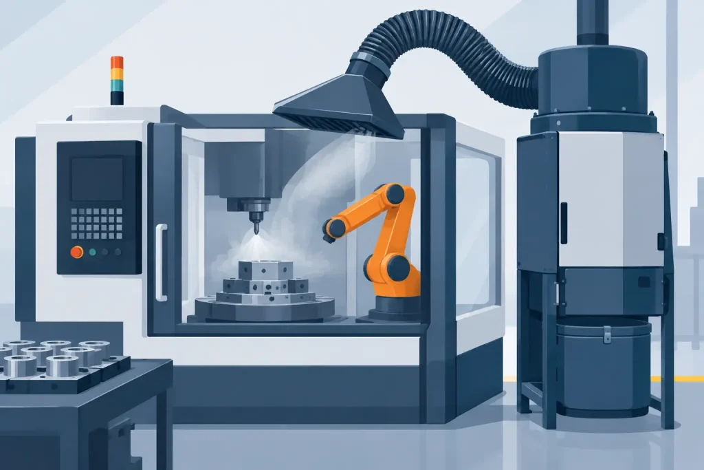
A CNC enclosure can appear clean while mist escapes every time the operator opens the door. That release is often the first visible sign that capture velocity, enclosure integrity, duct balance, or filter condition needs attention. This machining mist capture example shows how an engineered system can control coolant aerosol at the machine source while supporting worker exposure control, equipment uptime, and defensible maintenance records.
The machining mist capture example
Consider a plant operating four enclosed vertical CNC machining centers, each using high-pressure water-miscible coolant for aluminum and steel components. The machines run two shifts, with frequent door openings for part changeover, inspection, and tool adjustments. A light haze is visible around the cell by mid-shift, residue is collecting on nearby electrical cabinets, and operators report odor and throat irritation.
The initial response might be to install a large general exhaust fan above the area. That approach can dilute some airborne mist, but it does not reliably capture the aerosol at its release point. It can also pull conditioned air from the building, disturb adjacent processes, and leave oil residue inside roof ductwork. The correct engineering question is not simply how much air to exhaust. It is where the mist is generated, how it leaves the enclosure, and what airflow is required to keep it contained.
For this example, each machine is fitted with a dedicated connection at the upper rear portion of its enclosure. The extraction point is positioned to draw aerosol away from the operator access door and toward the mist collector without interfering with machine operation. The four branches connect to a common duct main and a centralized mist collection unit located outside the production area.
A centralized arrangement is not always the preferred choice. Individual collectors may be better where machines are widely separated, coolant types vary substantially, or production changes frequently. In a compact cell with similar machining duty, however, a central system can simplify discharge routing, maintenance access, and monitoring.
Start with the contaminant, not the collector
Machining mist is not one uniform contaminant. High-speed spindle operation and coolant pressure can produce a mixture of larger droplets, fine aerosol, vapor, and smoke-like particulate. The particle distribution changes with cutting speed, coolant chemistry, tool condition, enclosure leakage, and whether the machine is cutting dry, near-dry, or flooded.
In this example, a field audit begins with machine observation rather than a catalog selection. The engineering team records spindle speeds, coolant pressure, cycle duration, door-open frequency, existing fan operation, and visible leakage paths. They also inspect whether cable entries, access panels, chip conveyor openings, and automatic loading interfaces compromise enclosure containment.
This distinction matters because a mist collector can have adequate airflow on paper while still failing at the machine. If the enclosure is leaking near the operator side, the extracted air may take the path of least resistance through another opening. Improving a gasket, closing an unused service port, or adding a simple baffle may improve actual capture more than increasing fan capacity.
The design basis should also identify the metalworking fluid. Water-soluble coolant may create a different filtration and drainage challenge than neat cutting oil. Neat oil applications can generate sticky coalesced liquid and, at elevated temperatures, may require consideration of fire risk and suitable protective measures. A system designed for coolant mist should not be assumed suitable for combustible metal dust, welding fume, or solvent vapor without separate hazard evaluation.
Airflow and ductwork must work as one system
For the four-machine cell, the required airflow is established from the enclosure openings, internal air movement, and the need to maintain inward airflow at likely escape points. A practical design may use controlled branch airflow to each CNC machine rather than allowing the nearest machine to consume most of the fan capacity.
Balancing dampers are installed at each branch, with access provided for future adjustment. Duct velocities are selected to keep collected liquid moving toward drainage points while avoiding unnecessary pressure loss and noise. Horizontal duct runs are minimized where possible, and the duct is arranged with adequate slope and drains so accumulated coolant or oil does not pool in low sections.
Poor duct design creates predictable operating problems. Oversized ducts can allow liquid to settle. Undersized ducts increase static pressure, fan energy use, and sound levels. Sharp elbows immediately at a machine connection can reduce effective capture, while unsealed joints may release mist back into the building. The ductwork should be fabricated, supported, and sealed as part of the capture system, not treated as a secondary installation detail.
At the collector, the fan is selected against the total system resistance at the required operating flow, including machine connections, duct length, elbows, filters, silencers where needed, and a realistic allowance for filter loading. Fan selection at a clean-filter condition alone can lead to falling airflow as filters accumulate contaminant.
Filtration should match the mist loading
A typical staged mist collector for this application uses impingement or pre-separation sections to remove larger droplets, followed by coalescing filter media for finer aerosol. Collected liquid drains to a sump or recovery container for managed disposal or reuse where process controls permit. A final high-efficiency stage may be appropriate when fine aerosol control is required, but it adds pressure drop and must be justified by exposure, process, and discharge requirements.
The filter arrangement is selected around real operating conditions. A machine producing primarily large droplets may benefit from effective pre-separation and drainage. A high-speed application generating very fine aerosol may require more coalescing surface area and a final polishing stage. Installing a high-efficiency final filter without addressing upstream liquid loading can cause premature loading and unnecessary replacement cost.
Discharge location also requires engineering review. The outlet should be located to prevent re-entrainment into outdoor air intakes, doors, or neighboring work areas. Where local environmental permits, building codes, or customer standards apply, the final discharge arrangement should be documented before installation. If the plant is outside the United States, the applicable occupational and environmental requirements may differ and should be assessed in the project compliance register.
Commissioning turns an installation into a control measure
The system should not be considered complete when the collector starts. Testing and commissioning establish whether each machine receives its intended airflow and whether the enclosure remains under effective negative pressure during representative cutting conditions.
For this CNC cell, commissioning should include these five deliverables:
- Airflow measurement at each branch and confirmation of balanced flow across all four machines.
- Static pressure readings across key system points and across each filter stage.
- Smoke visualization or equivalent qualitative testing at enclosure openings and operator access areas.
- Verification of drainage, sump operation, duct cleanliness access, and safe maintenance clearances.
- A baseline report recording fan speed, airflow, pressure drop, motor current, and any corrective actions.
Smoke testing is especially valuable because it makes airflow behavior visible. It may show that capture is effective with doors closed but reverses during automatic pallet loading, or that a chip conveyor opening needs a local curtain or modified hood geometry. Those findings should lead to corrective work before final acceptance, not be left to operators to manage informally.
Where worker exposure concerns exist, personal or area sampling should be planned separately from ventilation commissioning. The two activities answer different questions. Airflow testing verifies system performance; exposure monitoring assesses what workers actually breathe over the relevant work period. In the United States, mineral oil mist has an OSHA permissible exposure limit, while other metalworking fluid aerosols may require assessment against applicable company, state, or recommended health criteria.
Maintenance data protects long-term performance
Mist collection performance declines gradually, which makes routine inspection essential. Filter pressure drop, branch static pressure, fan current, drainage condition, and visible leakage should be tracked against the commissioning baseline. A sudden pressure increase can indicate filter loading or a blocked drain. A pressure decrease may point to a damaged filter, open access door, duct leak, or fan issue.
Maintenance intervals should be based on operating hours and measured condition, not only a fixed calendar schedule. A cell that runs high-pressure coolant continuously will load filters differently from a machine used intermittently for short finishing cycles. Maintenance personnel should have safe access to filters and drain points, with documented procedures for handling collected fluid and contaminated media.
Master Jaya Group approaches mist control as a lifecycle engineering responsibility: field auditing, system design, fabrication, installation, testing and commissioning, performance monitoring, spare parts support, and servicing. That approach gives plant teams a traceable basis for keeping a capture system effective after the project handover.
The practical value of this machining mist capture example is not the exact fan size or filter model. Those must be determined from the machine layout and process conditions. The value is the sequence: contain the source, establish controlled airflow, remove mist in stages, verify performance, and keep records that show the system is still doing its job. When operators can open a CNC door without walking into a visible plume, the plant is closer to an air-control program that protects both production and people.