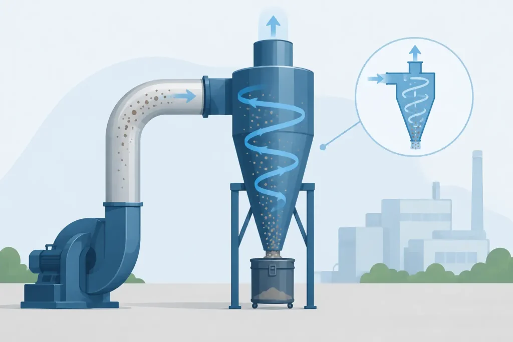
A cyclone that looks adequately sized on a layout drawing can still become the weak point in an air pollution control system. When engineers ask how to size cyclone separators, the answer is not simply to select a barrel diameter from an airflow table. The cyclone must be sized around the real process gas volume, dust characteristics, target particle capture, available fan static pressure, and the compliance performance required at the discharge point.
For abrasive, coarse, or high-loading dust streams, a properly engineered cyclone can reduce the burden on downstream pulse-jet dust collectors, protect filter media, and recover usable product. For fine particulate emissions, however, a cyclone alone may not deliver the outlet concentration needed for an emissions limit. Sizing must therefore begin with the whole collection system, not the cyclone in isolation.
Start With the Actual Gas Flow Rate
Cyclone capacity is governed primarily by volumetric gas flow. Establish the design flow in actual cubic feet per minute (ACFM) at operating temperature and pressure, rather than relying only on standard air volume or nameplate fan capacity.
Process heat can materially increase gas volume. A cyclone serving a hot thermal process, for example, receives a much larger actual volume than the same mass of gas at ambient conditions. Moisture, duct leakage, dilution air, and changes in production rate also affect the operating flow. If these conditions are not captured during design, inlet velocity can fall below its effective range or rise high enough to cause excessive pressure loss and erosion.
The design flow should be based on the highest credible operating condition, with a defined allowance for process variation. This does not mean applying an arbitrary oversizing factor. An oversized cyclone may operate at too low a velocity and lose collection efficiency. A unit that is too small may create high pressure drop, fan instability, noise, and accelerated wear.
Before selecting cyclone dimensions, verify the airflow requirement at each pickup point. This includes hood face velocity, enclosure airflow, branch duct transport velocity, diversity between operating points, and expected leakage. In local exhaust ventilation systems, insufficient hood capture cannot be corrected by installing a larger cyclone downstream.
Establish the Dust Properties That Control Separation
Cyclones remove particles by centrifugal force. Their performance changes substantially with particle size, density, shape, and concentration. A material safety data sheet is useful, but it rarely provides enough information for final sizing.
A sound design basis identifies the particle-size distribution, especially the proportion below 10 microns. Coarse metal chips, foundry sand, grain fragments, and many mineral dusts can be well suited to cyclone separation. Fine welding fume, smoke, pigment dust, and light fly ash are more difficult because the smallest particles follow the gas vortex out of the outlet.
Bulk density should not be confused with true particle density. The latter has a stronger influence on centrifugal separation. A dense metallic particle is generally easier to separate than an equally sized low-density organic particle. Sticky, hygroscopic, or fibrous materials introduce different concerns: they can build up on cyclone walls, bridge in the hopper, or obstruct the rotary airlock.
Representative dust sampling is essential where the process changes by product grade, moisture content, or shift. Field auditing and stack sampling can provide the operating data needed to avoid selecting equipment from assumed values rather than measured conditions.
Select an Inlet Velocity, Then Derive Cyclone Size
A conventional high-efficiency cyclone commonly operates with inlet velocities in the approximate range of 3,000 to 4,000 feet per minute. The appropriate velocity depends on the cyclone geometry, dust abrasiveness, desired cut point, and available fan pressure.
The core relationship is straightforward:
Cyclone inlet area = design gas flow / selected inlet velocity
If a system requires 20,000 ACFM and the selected inlet velocity is 3,500 feet per minute, the required inlet area is approximately 5.7 square feet. The cyclone body diameter is then determined from the chosen geometry, because inlet width and height are normally set as proportions of the body diameter.
This is where geometry matters. High-efficiency designs use a smaller inlet and longer gas path to increase centrifugal action. They can capture finer particles, but they also create higher pressure drop. High-capacity designs use a larger inlet and lower pressure drop, but their collection performance at smaller particle sizes is lower.
A supplier should state which geometry is being proposed and provide its expected performance curve. A single efficiency percentage without a particle-size basis is not sufficient for engineering approval.
Use Pressure Drop as a Design Constraint
Cyclones operate by consuming pressure. Typical pressure drops may range from roughly 2 to 8 inches of water column, depending on design and operating velocity. The fan must overcome the cyclone loss together with hood, duct, filter, silencer, stack, and discharge losses.
Higher inlet velocity can improve separation to a point, but it also raises pressure loss sharply. The added fan energy remains a lifecycle cost, and excessive velocity can wear through inlets, cones, and elbows when the dust is abrasive. A lower-pressure cyclone may be the better choice when the downstream collector provides the final fine-particle filtration.
Fan selection must be based on the full system resistance curve. Testing and commissioning should confirm actual airflow, differential pressure, motor load, and fan operating point after installation. A cyclone can be correctly fabricated yet underperform because a fan is operating away from its duty point.
Size for the Required Cut Point, Not Just Total Efficiency
Cyclone performance is often described by its cut size, commonly expressed as d50. This is the particle size at which the cyclone collects approximately 50 percent of particles. A smaller d50 generally indicates better fine-particle separation.
For practical design, request grade efficiency data showing predicted capture across particle-size ranges. For example, a cyclone may collect most particles above 20 microns while allowing a significant fraction of particles below 5 microns to pass through. Whether that is acceptable depends on the process and the required outlet concentration.
If final emissions must meet a tight particulate limit, the cyclone may need to function as a pre-cleaner ahead of a baghouse, cartridge collector, wet scrubber, or electrostatic precipitator. This arrangement can reduce dust loading and spark risk at the final collector while improving filter life. Trying to force a cyclone to replace a high-efficiency filter system is often a false economy.
Decide Between One Large Cyclone and Multiple Cyclones
A single cyclone can be practical for moderate airflows and coarse dust. At higher flows, a multi-cyclone arrangement may provide better control of velocity and particle separation because each tube handles a smaller gas volume.
Multiple small-diameter cyclones can achieve a finer cut point than one large-diameter cyclone operating at the same total flow. The trade-off is greater fabrication complexity, more potential wear points, and the need to distribute airflow evenly across all tubes. The hopper and discharge system must also handle dust from every cyclone without re-entrainment.
A multi-cyclone is often considered for boiler flue gas, grain and feed processing, foundry operations, and other applications with high dust loading. The decision should consider turndown. If only a fraction of the process operates during some shifts, a fixed multi-cyclone bank may experience low velocities unless airflow control or staged operation is included.
Design the Hopper and Dust Discharge as Part of the Cyclone
Cyclone separation fails when collected dust is allowed to re-enter the gas stream. The hopper must maintain a stable dust seal and provide sufficient slope for the material to flow to discharge. Flat hopper angles, undersized outlets, and unsuitable rotary valves are common reasons for plugging and carryover.
The discharge device must match the dust. A rotary airlock can maintain pressure isolation, but its clearance, material construction, and speed must suit the dust’s abrasiveness and flow behavior. Screw conveyors, double-dump valves, or enclosed drum collection may be more appropriate in certain installations.
Where combustible dust is present, the cyclone, hopper, ducting, and downstream equipment must be evaluated as a dust hazard system. Grounding, explosion venting, isolation, and safe dust-handling provisions should be engineered according to the applicable codes and site risk assessment. These measures are not optional add-ons after fabrication.
Verify Materials, Wear Protection, and Access
Cyclone wall thickness and material selection should reflect gas temperature, corrosion potential, and abrasion rate. High-velocity coarse dust can quickly erode the inlet, barrel transition, cone, and hopper. Wear liners, replaceable inlet sections, abrasion-resistant steel, or ceramic protection may be justified where maintenance access is difficult or unplanned shutdowns carry high production cost.
Inspection doors should be located where buildup and wear are most likely. Differential pressure measurement across the cyclone is also valuable for ongoing monitoring. A falling pressure drop can indicate air leakage or reduced flow; a rising pressure drop may indicate blockage in the outlet, hopper, or downstream system.
Confirm Performance After Installation
Final sizing should be validated through commissioning, not assumed from calculations. Measure airflow at representative operating conditions, record static pressure at key points, inspect dust discharge, and confirm fan performance. Where regulatory compliance applies, conduct stack sampling using an appropriate test method and retain the results with operating records.
Master Jaya Group approaches cyclone projects as part of an engineered air pollution control system, including design, fabrication, installation, testing and commissioning, field auditing, and after-sales support. The objective is not merely to install a cyclone, but to maintain controllable airflow, reliable dust handling, and defensible emissions performance over the equipment lifecycle.
The most useful next step is to build a design data sheet from measured airflow, temperature, dust loading, particle-size distribution, and required outlet condition. With those inputs in hand, cyclone sizing becomes an engineering decision that protects both plant uptime and clean-air accountability.