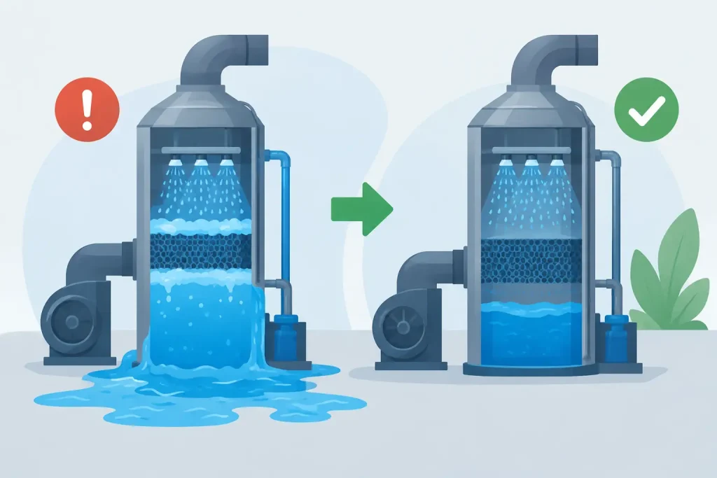
A packed tower scrubber can appear to be operating normally until the differential pressure rises, liquid carryover reaches the outlet duct, and stack results begin to drift. Scrubber flooding causes are rarely limited to one failed component. They usually reflect an imbalance between gas velocity, liquid loading, packing condition, and the actual process duty the system is being asked to handle.
Flooding is not simply a maintenance inconvenience. It can reduce contaminant absorption, overload mist eliminators, create corrosion and liquid carryover downstream, and force unplanned production constraints. For facilities operating under air-permit conditions, it also creates a documentation problem: a scrubber that cannot maintain stable operating parameters cannot provide defensible evidence of continuous emissions control.
What Scrubber Flooding Actually Means
In a countercurrent packed tower, contaminated gas enters from the lower section and moves upward through the packing. Scrubbing liquid is distributed from the top and flows downward across the packing surface. The large wetted surface area enables mass transfer, allowing soluble gases, fumes, or particulate matter to be captured by the liquid.
Flooding begins when upward gas force interferes with the downward liquid flow. Liquid holdup increases within the packing, pressure drop rises, and the bed can no longer drain at the required rate. At more severe conditions, liquid may be pushed upward, entrained into the mist eliminator, or carried into the outlet ductwork.
A flooded tower does not always fail suddenly. Many systems operate close to their hydraulic limit for weeks before a process change, fouled packing, or damaged distributor pushes them beyond stable operation. This is why operating trend data is more useful than a single pressure reading taken during an inspection.
Primary Scrubber Flooding Causes
Excessive gas flow or gas velocity
The most common cause is gas flow beyond the tower’s design capacity. Higher gas velocity increases frictional resistance against descending liquid. Once the gas momentum approaches the point at which it supports or lifts the liquid film, flooding begins.
This often occurs after production expansion, installation of a larger process fan, modifications to branch ducting, or the addition of new pickup points. In some facilities, dampers are opened to resolve poor capture at a hood, unintentionally increasing total airflow through a scrubber that was not designed for the added volume.
Fan performance should be verified against the original system duty, not assumed from motor speed or damper position. Field airflow measurement, static pressure testing, and review of duct balance are necessary before concluding that the scrubber itself is undersized.
Excessive liquid circulation rate
More recirculating liquid does not automatically improve scrubber efficiency. When the liquid-to-gas ratio exceeds the packing and distributor design range, the packing retains too much liquid. The available void space for upward gas movement narrows, causing pressure drop to climb rapidly.
High liquid flow can result from an incorrectly selected pump, a replacement pump with a larger impeller, an improperly adjusted bypass, or control settings that keep the pump at maximum output regardless of process demand. In systems with automatic pH control or make-up water control, a malfunctioning valve can also increase liquid volume in the recirculation loop.
The appropriate liquid rate depends on the contaminant, reagent chemistry, packing type, tower diameter, and required removal efficiency. It should be confirmed against the engineered design basis during testing and commissioning, rather than adjusted by trial and error.
Fouled, damaged, or incorrectly installed packing
Packing must provide contact area while preserving open space for gas and liquid movement. Scale, sludge, polymer deposits, oil contamination, biological growth, and particulate accumulation reduce that open area. Even modest fouling can change the hydraulic behavior of a packed bed substantially.
Packing damage is equally significant. Random packing may settle, break down, or become compressed during maintenance. Structured packing can be installed in the wrong orientation, damaged by improper access, or distorted by unsupported bed sections. A collapsed packing support grid creates a localized restriction that can lead to rapid flooding.
Facilities treating metalworking fume, sticky organic vapor, oil mist, or dust-laden gas should not assume that a packed tower can act as both a primary particulate collector and a gas absorber. Effective upstream separation, such as a cyclone, wet pre-cleaner, or properly engineered dust collection system, may be needed to protect the packing from premature fouling.
Poor liquid distribution
A packed bed performs only as well as its liquid distributor. If nozzles are blocked, misaligned, worn, or supplied at inadequate pressure, the liquid may channel through a small part of the bed. Other sections become dry while overloaded zones retain excess liquid and approach flooding.
Distribution problems are especially likely after maintenance, chemical precipitation, nozzle replacement, or low-flow operation. A tower may show acceptable overall circulation flow at the pump discharge while the distributor is delivering poor coverage at the top of the bed.
Inspection should verify nozzle condition, spray pattern, distributor level, header pressure, and equal flow across the tower cross-section. Where practical, a controlled water test during shutdown provides direct confirmation of coverage before the system returns to service.
Mist eliminator blockage and outlet restrictions
Flooding can be caused or worsened by restrictions above the packed bed. A plugged mist eliminator increases pressure drop and limits gas discharge. Deposits on chevron blades, mesh pads, outlet transitions, dampers, or ductwork can create backpressure that changes the tower’s operating point.
A mist eliminator may plug because of excessive liquid carryover, poor wash-water coverage, solids in the recirculation liquor, or corrosion products from upstream equipment. Replacing the mist eliminator without addressing the source of deposits often leads to repeat failures.
Foaming, solids buildup, and chemical imbalance
Certain process contaminants and chemical reagents promote foam formation. Oils, surfactants, resins, organic compounds, and improperly controlled treatment chemistry can create stable foam within the sump or packing. Foam occupies volume, disrupts drainage, and can be carried upward into the demister.
High dissolved solids and suspended solids also increase the likelihood of scaling and nozzle plugging. A scrubber treating acidic or alkaline gases requires controlled reagent concentration, pH, blowdown, and make-up water quality. The right chemistry is process-specific. Increasing chemical feed without confirming reaction demand can create deposits and operational instability rather than better removal performance.
Warning Signs That Require Investigation
Differential pressure is the most useful early indicator, particularly when it is trended against fan speed, process load, and recirculation flow. A gradual increase usually points to fouling, while a sudden change may indicate a blocked distributor, damper movement, pump issue, or production upset.
Other warning signs include visible liquid at the outlet duct, increased fan amperage, unstable sump level, unusual pump noise, reduced exhaust capture at process hoods, wet stack discharge, and recurring demister replacement. Stack appearance alone is not a reliable diagnostic tool, but it should prompt an operating review and, where required, stack sampling.
A Practical Diagnostic Sequence
The correct response is to establish the actual operating condition before changing multiple variables. Start by recording gas flow, fan static pressure, scrubber differential pressure, recirculation flow, pump discharge pressure, sump level, pH, conductivity, reagent feed rate, and production throughput. Compare these values with the approved design data and previous stable operating trends.
Next, inspect accessible restrictions. Confirm damper position, outlet duct condition, mist eliminator cleanliness, wash-water operation, pump rotation, valve alignment, and bypass status. If the external checks do not explain the pressure increase, schedule an internal inspection of the distributor, packing, support grid, and sump.
Do not reduce fan speed as a permanent correction unless engineering review confirms that capture performance remains adequate. Lower airflow may stop flooding while allowing fumes, dust, or vapor to escape at the source. The objective is stable scrubber hydraulics and effective source capture, not simply a lower pressure-drop reading.
Corrective Actions That Protect Compliance
The remedy depends on the confirmed cause. Excess airflow may require duct rebalancing, fan control adjustment, added scrubber capacity, or a parallel treatment train. Excess liquid flow may be corrected through pump trimming, variable-speed control, calibrated flow restriction, or redesign of the recirculation loop.
Fouled packing may need chemical cleaning or replacement, but the upstream contaminant source must also be addressed. If solids are entering the scrubber, add suitable pre-separation and improve blowdown management. If the tower is undersized for current production, replacing packing alone will not create enough hydraulic capacity.
After corrective work, perform testing and commissioning under representative production conditions. Verify pressure drop, flow balance, liquid distribution, pH control, and visible carryover. For regulated facilities, retain calibration records, inspection findings, operating trends, maintenance documentation, and stack sampling results where applicable. These records support both internal reliability programs and regulatory inspections.
Master Jaya Group approaches scrubber performance as a lifecycle responsibility, combining engineering review, fabrication, installation, testing and commissioning, field auditing, spare parts support, and performance monitoring. This approach is particularly valuable when a flooding event points to a system-wide issue rather than a single component failure.
A scrubber should operate with enough margin to absorb normal production variation without crossing its flooding point. Maintaining that margin through disciplined monitoring, timely inspection, and engineering-based modifications gives plant teams a more reliable path to cleaner air and confident compliance.