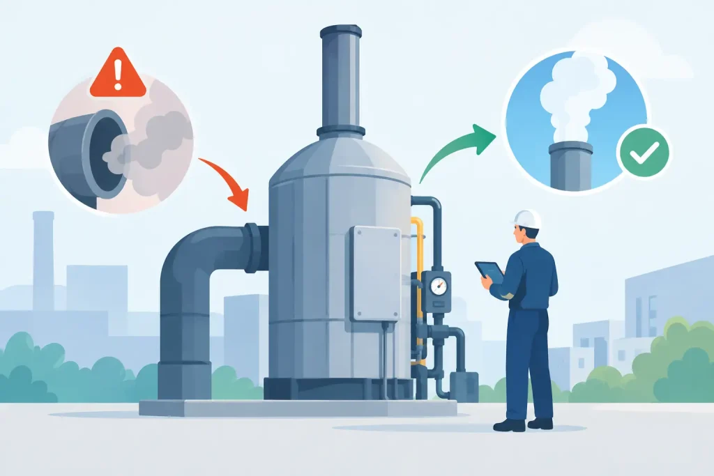
A regenerative thermal oxidizer can appear to be operating normally while quietly consuming excessive natural gas, losing VOC destruction performance, or creating a stack-test risk. Oxidizer efficiency problems rarely begin as a single catastrophic failure. More often, they develop through gradual changes in airflow, combustion, sealing, valve timing, media condition, or process loading. For plant managers and EHS leaders, the issue is not simply energy cost. It is the ability to demonstrate consistent emissions control under actual production conditions.
An effective response starts by separating two measurements that are often treated as one: destruction efficiency and thermal efficiency. They affect each other, but they are not interchangeable.
What Oxidizer Efficiency Actually Means
Destruction efficiency measures how effectively an oxidizer destroys regulated pollutants, typically volatile organic compounds, hazardous air pollutants, or odor-causing compounds. It depends on the established combustion principles of time, temperature, turbulence, and oxygen availability. If any of these conditions falls outside the validated operating range, outlet concentrations can rise even when the combustion chamber temperature looks acceptable.
Thermal efficiency measures how much process heat is recovered and reused. In an RTO, ceramic heat-transfer media captures heat from the clean outlet stream and transfers it to the incoming contaminated stream. High thermal efficiency reduces auxiliary fuel demand. A system may achieve acceptable destruction efficiency while suffering poor thermal efficiency, resulting in high gas consumption. Conversely, a unit can recover heat effectively but still fail to maintain the conditions needed for reliable pollutant destruction.
Compliance reviews should therefore assess both outcomes: verified outlet emissions and the operating data that explain fuel use, temperature stability, pressure drop, valve performance, and process airflow.
Common Oxidizer Efficiency Problems in Operating Plants
Incorrect Airflow and VOC Loading Assumptions
Oxidizers are designed around a defined exhaust volume, contaminant concentration, temperature, moisture level, and composition. Production expansion, new coatings, changed solvents, additional process hoods, or modified duct routing can move the actual duty far beyond the original design basis.
Excess airflow is a frequent cause of poor performance. It increases the energy required to heat the stream to destruction temperature and can shorten residence time. Too little airflow can create poor capture at the source, allowing fugitive VOCs or fumes into the work area while giving the oxidizer an artificially light load. In either case, the system must be evaluated as a complete capture, conveyance, and treatment system rather than as an isolated piece of equipment.
Variable-frequency drive settings, fan rotation, damper position, duct leakage, and unauthorized connections should all be checked against the approved design data. Field airflow measurements are more defensible than assumptions based on fan speed or nameplate capacity.
Combustion Chamber Temperature Instability
A temperature trend that fluctuates widely often points to burner control issues, inadequate fuel pressure, faulty temperature sensors, changing inlet conditions, or poorly tuned control logic. The average displayed temperature may still meet the operating setpoint, but short-duration drops can affect destruction performance.
Thermocouples deserve particular attention. A drifting sensor can lead the control system to reduce burner firing when the true chamber temperature is lower than indicated. Sensor location also matters. A measurement taken too close to a burner flame or hot refractory surface may not represent the mixed gas temperature through the chamber.
Burner inspection should include ignition reliability, flame safeguard status, combustion air supply, fuel train condition, flame pattern, and modulation response. Maintenance teams should record not only alarm events but also burner cycling frequency and temperature recovery time after process-load changes.
Worn or Leaking RTO Switching Valves
RTO valve performance has a direct effect on thermal recovery and emission control. Poppet valves, rotary valves, and diverter assemblies must direct process gas through the correct ceramic beds during each cycle. Leaking seals, worn seats, actuator faults, or incorrect switching timing can allow untreated inlet gas to bypass the intended flow path or allow clean gas to mix with contaminated gas.
This failure mode may be difficult to identify from a control-room screen alone. Signs include unexplained fuel increase, inconsistent bed temperature profiles, elevated outlet VOC readings, unusual pressure behavior during switching, or visible wear during shutdown inspection.
Valve timing should be verified during testing and commissioning and rechecked after control modifications. Preventive maintenance must include inspection of seals, mechanical linkages, actuators, limit switches, and compressed-air supply where pneumatic actuation is used.
Ceramic Media Fouling, Damage, or Channeling
Ceramic media is the heat-recovery core of an RTO. Over time, particulate matter, oil mist, condensable organics, siloxanes, or process residues can coat media surfaces. Fouling reduces heat transfer and increases pressure drop. If the pressure drop becomes excessive, fan energy rises and system airflow may decline.
Media damage creates a different problem. Cracked or displaced blocks can form channels that allow gas to pass through with less heat exchange. The unit may then require more burner fuel even though temperature controls appear stable. In severe cases, damaged media can restrict flow or contribute to uneven distribution across the bed.
The correct remedy depends on the contaminant. Some systems require upstream filtration, mist elimination, or preconditioning to prevent repeated fouling. Cleaning media without addressing the source of carryover usually produces only temporary improvement.
Inadequate Purge and Poor Duct Pressure Control
RTO purge cycles reduce the amount of untreated gas that remains in a bed when flow direction changes. If the purge flow is insufficient, improperly sequenced, or leaking through dampers and valves, a higher concentration of untreated gas can reach the outlet. This is especially significant where permits establish low outlet limits or where stack testing is conducted during variable production.
Duct pressure control also affects efficiency. Negative pressure at capture points may be necessary to contain VOCs, fumes, or odors. Yet excessive fan static pressure wastes energy, while insufficient pressure permits fugitive emissions. Fan curves, actual static pressure, damper settings, and duct condition should be reviewed together.
A Practical Diagnostic Process
A reliable investigation combines operating records with physical field verification. Begin by establishing a baseline during representative production, not during an unusually light shift or planned maintenance period. Review fuel consumption per unit of production, combustion chamber temperature, bed temperatures, inlet and outlet pressure, fan speed, valve cycle time, VOC monitor data where installed, and production rate.
Next, compare current conditions with the original process design basis and the latest permitted operating envelope. A change in raw material or solvent chemistry may alter heating value, moisture, halogen content, particulate loading, or combustion characteristics. These changes can require revised controls, upstream treatment, or equipment upgrades.
Field auditing should then verify airflow at collection points and key duct locations, identify leakage or corrosion, inspect valve assemblies and ceramic media where safe, and assess burner operation. Stack sampling provides independent performance evidence when required for regulatory reporting, permit verification, or corrective-action validation.
For facilities with continuous or periodic online monitoring, trend analysis is particularly valuable. One isolated high-temperature alarm may not be meaningful. A gradual increase in burner demand, pressure drop, or cycle-to-cycle temperature imbalance often reveals a developing mechanical or process problem before it becomes an emissions excursion.
Corrective Actions Should Protect Compliance and Uptime
The right corrective action is not always a major retrofit. Control tuning, thermocouple replacement, valve seal renewal, burner servicing, duct repair, or fan balancing can restore performance when the root cause is maintenance-related. However, a plant that has permanently increased exhaust flow or changed its solvent mix may require a larger combustion chamber, additional media capacity, upgraded fan capacity, a concentrator, or upstream filtration.
Any modification should be evaluated against the facility’s applicable air permit, monitoring requirements, and worker-exposure obligations. The change must also be documented through testing and commissioning. A repaired oxidizer that is not validated under representative process conditions leaves the facility without defensible evidence of performance.
Master Jaya Group approaches oxidizer troubleshooting as a lifecycle responsibility: field auditing, airflow assessment, system inspection, engineering review, testing and commissioning, stack sampling support, and ongoing performance monitoring. This integrated approach helps plants address the actual cause rather than repeatedly treating the visible symptom.
A well-maintained oxidizer should not force a choice between compliance and operating cost. When operating data, preventive maintenance, and process changes are reviewed together, the plant can protect destruction performance, control fuel use, and maintain the records needed to support confident environmental compliance.