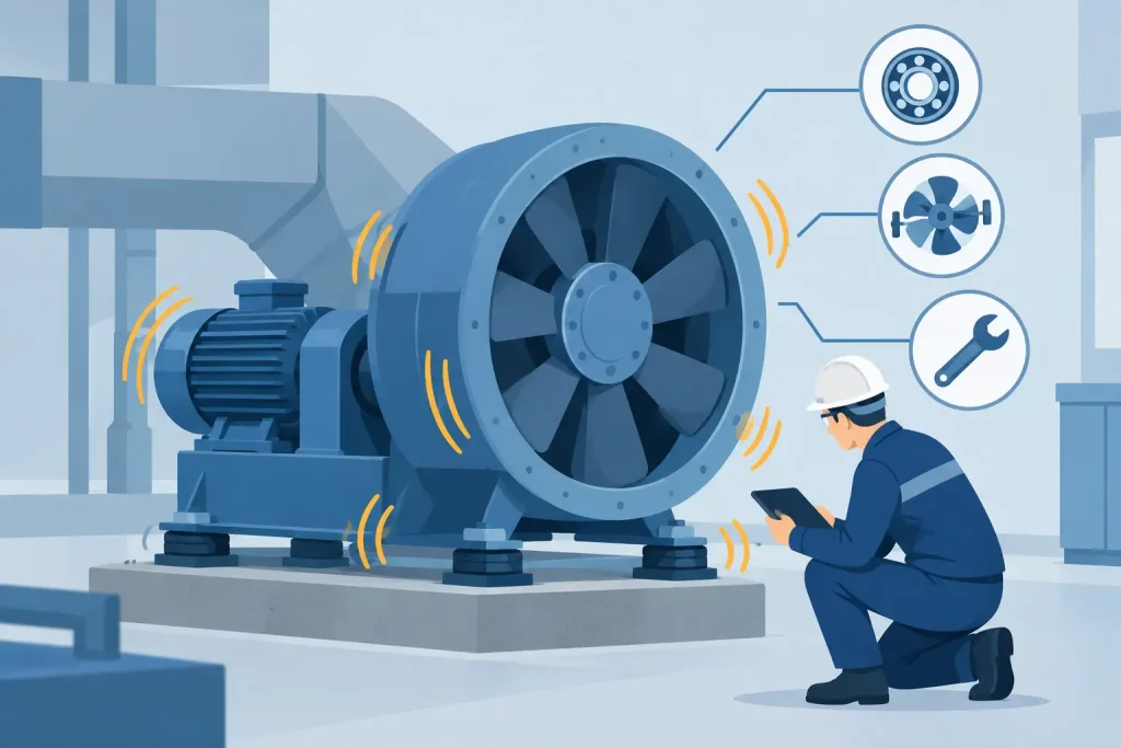
A fan that begins shaking after a shutdown, belt change, duct modification, or production increase is not merely creating a maintenance nuisance. Industrial fan vibration is often the earliest measurable sign that rotating equipment, airflow conditions, or supporting structures are moving outside their intended operating range. Left unresolved, it can progress from elevated bearing temperatures and poor suction to shaft damage, cracked foundations, unplanned shutdowns, and compromised worker-exposure control.
For facilities operating local exhaust ventilation, dust collection, scrubbers, thermal oxidizers, or process ventilation systems, stable fan operation is directly connected to system performance. The fan provides the pressure needed to capture contaminants at the source, convey them through ductwork, and maintain the designed airflow across control equipment. Vibration therefore requires a disciplined engineering response, not a temporary adjustment made simply to reduce noise.
Why Industrial Fan Vibration Requires Prompt Action
An industrial fan is designed around a specific combination of airflow, static pressure, speed, impeller geometry, drive arrangement, and structural support. When any one of these conditions changes, the resulting forces can be transmitted through the shaft, bearings, motor, casing, ductwork, and foundation.
The immediate effects may appear limited: a noisy bearing housing, a loose guard, or a visibly moving flexible connection. Over time, however, vibration can shorten bearing life, loosen fasteners, fatigue welds, damage impeller blades, and cause belt or coupling failures. In a dust collector or local exhaust ventilation system, the operational consequence may be reduced capture velocity at hoods and insufficient airflow at the point of emission.
This is why fan vibration should be assessed alongside airflow measurement, static-pressure readings, motor current, bearing temperature, and physical inspection. A vibration value alone does not identify the cause. Its amplitude, frequency, direction, operating condition, and trend over time provide the useful diagnostic picture.
Common Causes of Industrial Fan Vibration
Impeller imbalance
Imbalance is among the most frequent sources of fan vibration. Dust accumulation, product buildup, moisture, corrosion, blade wear, or a missing balance weight can shift the impeller’s center of mass away from the shaft centerline. As the fan rotates, that uneven mass creates a repeating centrifugal force, commonly observed at running speed.
Fans handling sticky dust, oil mist, animal feed, wood particles, or corrosive fumes are especially exposed to buildup and material loss. Cleaning may restore performance in some cases, but it is not always a complete correction. If the impeller has corroded, eroded, cracked, or been repaired by welding, dynamic balancing may be required before the fan is returned to service.
Misalignment and drive faults
Misalignment occurs when the motor and fan shafts are not correctly positioned relative to one another. On direct-drive units, angular or parallel misalignment at the coupling can create vibration, heat, and accelerated coupling wear. On belt-driven fans, incorrect sheave alignment, improper belt tension, worn belts, and eccentric sheaves can produce similar symptoms.
Over-tightening belts is a common but costly response to belt slip. Excessive tension increases radial loading on fan and motor bearings, which can create a secondary bearing problem. The correct approach is to verify sheave alignment, belt condition, belt type, and tension against the equipment manufacturer’s requirements.
Bearing deterioration and shaft damage
Bearing defects often create higher-frequency vibration than simple imbalance and may be accompanied by rising temperature, grease leakage, abnormal noise, or discoloration around the bearing housing. Contamination, inadequate lubrication, incorrect grease selection, over-greasing, and excessive belt loading all contribute to premature failure.
A bent shaft, worn shaft fit, damaged keyway, or loose bearing fit can also produce repeatable vibration. These faults should not be corrected by adding shims or increasing lubrication alone. The fan must be inspected during a planned shutdown, with shaft runout and bearing fits checked against acceptable tolerances.
Aerodynamic instability and operating-point problems
Not every vibration issue begins with a mechanical defect. A fan can run smoothly at one airflow condition and become unstable when dampers are throttled, filters are blinded, ductwork is changed, or process demand falls outside the original design basis.
Centrifugal fans operating near stall can experience fluctuating pressure and airflow. This aerodynamic instability may cause pulsation, rumbling, casing movement, and vibration that varies as dampers are adjusted. In these cases, balancing the impeller will not solve the underlying problem. The system curve, fan curve, damper position, duct losses, and actual airflow must be reviewed together.
Structural weakness, resonance, and duct loading
A fan can be mechanically sound yet still vibrate excessively if its base frame, foundation, steel platform, isolation mounts, or duct supports are inadequate. Resonance occurs when an excitation frequency from the rotating fan or airflow pulsation approaches the natural frequency of the structure. Vibration can then increase sharply, even when the original forcing level is modest.
Unsupported ductwork and poorly installed flexible connectors are frequent contributors. Duct weight should not be transferred into the fan inlet or outlet casing unless the equipment has been specifically designed for that load. Flexible connections should isolate movement, not compensate for major misalignment or carry duct loads.
A Practical Diagnostic Sequence
A reliable diagnosis begins with confirming operating conditions before parts are replaced. Record fan speed, motor current, damper position, airflow, static pressure, bearing temperature, and vibration readings at consistent locations. If available, compare these values with testing and commissioning records, baseline condition-monitoring data, and the fan manufacturer’s performance curve.
The inspection should then cover the impeller, inlet cone, shaft, bearings, coupling or belts, motor feet, base frame, anchor bolts, vibration isolators, guards, flexible connectors, and adjacent duct supports. Look for dust buildup, rubbing marks, cracks, loose hardware, corrosion, distorted components, and evidence that the fan casing is under external stress.
Vibration analysis becomes more valuable when measurements are taken in horizontal, vertical, and axial directions at both fan and motor bearings. A dominant running-speed frequency may point toward imbalance, while axial vibration can suggest misalignment. Higher-frequency patterns may indicate bearing defects. These are diagnostic indicators, not stand-alone conclusions. Field observations and operating data must confirm the likely fault.
For critical ventilation and air-pollution-control equipment, trend monitoring is more effective than reacting only after vibration becomes severe. An online monitoring layer can provide early warning when vibration, bearing temperature, motor load, or airflow shifts away from established limits. This helps maintenance teams plan correction before equipment failure affects production or compliance performance.
Corrective Actions Must Match the Root Cause
The right corrective action depends on the verified cause. A contaminated impeller may need controlled cleaning followed by dynamic balancing. A misaligned drive requires precision alignment and a check for soft foot at the motor base. Bearing replacement must include an investigation into lubrication practice, shaft condition, and loading, or the replacement bearing may fail prematurely.
When the root cause is aerodynamic, the solution may involve changing fan speed, correcting duct restrictions, revising damper control, replacing overloaded filters, or selecting a fan better suited to the actual system duty. Where resonance is present, structural reinforcement, revised support spacing, changes in isolator stiffness, or a controlled speed change may be necessary.
Do not accept a lower vibration reading as proof that the system is healthy if airflow has dropped substantially. A ventilation fan can appear quieter because it is operating at reduced load while no longer delivering the capture performance required at process hoods. Confirm the correction with airflow and static-pressure testing, then document the findings for maintenance and compliance records.
Protecting Ventilation Performance Over the Equipment Life Cycle
Fan reliability begins during design and installation. The selected fan must suit the expected airflow, pressure, temperature, particle characteristics, corrosion risk, and future operating range. Installation should include proper foundation design, duct support, alignment, balancing, electrical checks, and testing and commissioning under representative process conditions.
After commissioning, a planned service program should address cleaning intervals, belt and coupling inspection, lubrication control, fastener checks, vibration trending, and periodic airflow verification. For regulated local exhaust ventilation systems, these records support defensible maintenance decisions and help demonstrate that control measures remain effective for worker exposure and emissions management.
Master Jaya Group approaches fan-related performance issues as part of the full air-pollution-control system, not as an isolated mechanical repair. Field auditing, airflow assessment, equipment servicing, and performance monitoring should work together to protect both fan reliability and the clean-air result the system was installed to deliver.
When a fan begins to vibrate, treat it as a condition that deserves measurement, investigation, and documented correction. A timely engineering response can preserve equipment life, stabilize process ventilation, and prevent a manageable warning from becoming an avoidable compliance and production event.