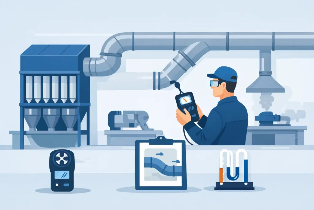
A dust collector ductwork balance testing procedure is not a final paperwork exercise after installation. It is the field verification that confirms every hood, branch, and process connection receives the airflow assumed during system design. When balance is poor, the dust collector may appear to be running normally while the furthest pickup point fails to capture dust, worker exposure increases, and duct deposits begin to build.
For plant managers, EHS leaders, and maintenance teams, the objective is straightforward: demonstrate that the local exhaust ventilation system is capturing contaminants at the source and conveying them safely to the collector. The record must be defensible, repeatable, and useful for future maintenance decisions.
Why Ductwork Balance Testing Matters
A dust collection system operates as an integrated network. The fan creates pressure, ductwork distributes airflow, hoods capture contaminants, and the collector separates particulate from the airstream. A restriction, open blast gate, leaking access door, incorrectly sized branch, or overloaded filter can change the airflow distribution across the entire system.
The highest-risk condition is often not a total fan failure. It is a system that has adequate airflow at easy, short branches but inadequate airflow at remote or high-resistance hoods. Operators may see dust escaping at only one transfer point, grinder, bagging station, or mixing vessel. That single failure point can affect housekeeping, product quality, equipment reliability, and employee exposure performance.
Balance testing supports commissioning, post-modification verification, periodic LEV assessment, and troubleshooting. It also establishes baseline readings for fan static pressure, duct velocity, hood airflow, and collector pressure drop. Without baseline data, a maintenance team has no reliable way to distinguish normal system aging from a meaningful loss of performance.
Preparation Before the Balance Test
Balance testing should be performed under representative operating conditions. Test results gathered while process equipment is idle, dampers are temporarily closed, or the dust collector is operating with freshly cleaned filters may not represent actual plant conditions.
Before measurements begin, confirm the system configuration against the approved drawings or a verified field sketch. Identify each hood, branch duct, blast gate, main duct, fan inlet and discharge, dust collector, and discharge point. Number the test locations clearly so readings can be traced to a specific process source.
The field team should inspect the system for visible defects before taking readings. Common issues include disconnected flex duct, damaged hoods, accumulated dust in horizontal duct runs, leaking clean-out doors, partially closed isolation dampers, and incorrectly positioned blast gates. Correcting obvious defects first prevents the test from becoming a record of avoidable failures.
Instrumentation must be suitable for the measurement range and maintained under a documented calibration program. Typical instruments include a Pitot tube with inclined or digital manometer, thermal or rotating vane anemometer where appropriate, differential pressure gauge, tachometer, and smoke generator for qualitative capture checks. Pitot traverses are generally preferred in round ductwork because they provide a more representative average velocity than a single-point reading.
Dust Collector Ductwork Balance Testing Procedure
1. Confirm the operating condition
Operate the production equipment and dust collector in the normal mode that creates the highest expected air demand. Confirm whether all pickup points are intended to operate simultaneously. If the design relies on selective operation through blast gates or automatic dampers, document that sequence before testing.
Record the fan speed, motor current, filter-cleaning status, hopper condition, and collector differential pressure. A high pressure drop across a pulse-jet dust collector can indicate loaded filter media or ineffective pulse cleaning. A low pressure drop can also require investigation, particularly if it suggests damaged filters, air bypass, or insufficient dust loading.
2. Measure airflow at each hood or branch
Start at the individual pickup points. Measure face velocity, slot velocity, or branch duct airflow based on the hood type and available access. For enclosed hoods, calculate the airflow needed to maintain inward airflow at openings. For open capture hoods, assess whether measured airflow and observed capture behavior are suitable for the contaminant release pattern.
Document the actual airflow in cubic feet per minute, duct velocity in feet per minute, and the hood or branch identification. The required velocity depends on the material being conveyed. Fine, dry dust may remain suspended at lower transport velocities than dense metal chips, wet particulate, or abrasive material. A single velocity target should not be applied indiscriminately across different processes.
Where duct access permits, perform a Pitot tube traverse at a straight duct section with adequate distance from elbows, branches, dampers, and transitions. Turbulence affects measurement accuracy. If ideal traverse locations are unavailable, record the limitation and use the best available method consistently.
3. Calculate and compare system airflow
Calculate airflow using the measured average duct velocity and duct cross-sectional area. Compare the actual airflow at each branch with the design airflow, then compare the sum of branch airflows with the measured main duct airflow. Minor differences can occur due to measurement uncertainty and air leakage, but significant discrepancies require investigation.
This comparison frequently identifies the root problem. If the main duct airflow is low, the issue may be fan capacity, fan rotation, belt condition, variable frequency drive settings, system resistance, or collector loading. If the main airflow is acceptable but one branch is low, the cause is more likely branch resistance, damper position, blockage, or poor duct geometry.
4. Adjust the system in a controlled order
Balancing is an iterative process. Start with branches receiving more than their design airflow, usually those closest to the fan or those with the lowest resistance. Add resistance gradually by adjusting dampers, then retest the affected branch and the remaining critical branches.
Do not use excessive damper closure as a permanent substitute for poor duct design. A heavily throttled branch increases energy demand and may create noise, abrasion, or unstable operation. If the imbalance is substantial, the proper corrective action may be a duct modification, branch resizing, hood redesign, additional fan capacity, or revised operating sequence.
Each adjustment changes the system curve. Recheck the furthest and most demanding pickup points after every material adjustment. The final setting should deliver required airflow to all active hoods while keeping fan operation within the motor and fan performance limits.
5. Verify capture and containment at the source
Airflow figures are necessary, but they are not the only acceptance criterion. Use smoke visualization, where safe and appropriate, to observe whether airflow enters the hood and whether contaminants can escape due to cross-drafts, operator position, moving equipment, or thermal currents.
A hood can meet a nominal duct velocity while still performing poorly if it is too far from the emission source or has an unsuitable opening geometry. Conversely, increasing fan airflow may not solve a capture problem caused by poor hood placement. This is why field auditing must consider the process itself, not only duct measurements.
6. Record final readings and system settings
The final test report should identify the system, process conditions, instrument details, test locations, measured values, calculated airflow, fan data, collector pressure drop, damper positions, and observed deficiencies. Include the drawing or schematic used for the test and clearly state any assumptions or inaccessible locations.
For compliance-driven facilities, the report should separate measured facts from recommendations. It should state whether the tested system achieved the specified design criteria and identify corrective actions where it did not. This documentation supports LEV performance review, maintenance planning, internal EHS audits, and discussions with regulatory authorities.
Common Findings That Require Corrective Work
Ductwork balance testing often reveals conditions that cannot be solved by adjustment alone. Common examples include undersized branches, long flexible connections, abrupt elbows near hoods, air leakage at access doors, clogged spark arrestors, dust accumulation in ducts, worn fan impellers, and filter media approaching its service limit.
A collector upgrade may be justified when process capacity has increased beyond the original design basis. Adding new machines to an existing header without recalculating airflow and static pressure is a frequent cause of poor suction. The dust collector may still meet an outlet emissions target while the local extraction system fails to control dust at the workplace.
Corrective work should be followed by repeat testing. A repair is not verified until airflow, capture performance, and system pressures confirm that it has produced the intended result.
Keeping the System Balanced After Commissioning
A balanced system can drift out of balance over time. Filter loading, fan wear, duct abrasion, product changes, unplanned branch additions, and changes in operating schedules all affect airflow. Establishing routine checks at critical hoods and tracking collector differential pressure enables maintenance teams to identify performance loss before it becomes a production or exposure incident.
Master Jaya Group approaches dust collection as a lifecycle responsibility: engineering, fabrication, installation, testing and commissioning, field auditing, performance monitoring, and after-sales service should work as one controlled process. The most useful balance test is therefore not a one-time certificate. It is a practical baseline that helps the plant protect people, maintain uptime, and act early when the system begins to change.